
Location -> Products -> Temperature -> Thermocouple and Thermal Resistance -> Thermocouple(Thermal Resistance) With Temperaturer
Type:thermocouple (thermal resistance) with temperature transmitter
Illustrate:It is usually connected with display meter, recording meter, computer, etc. to directly measure temperature of liquid, vapor, gas and solid surface ranging from -200℃ to 1300℃ with explosives such as hydrocarbon on production spot, with output of 4~20mA.
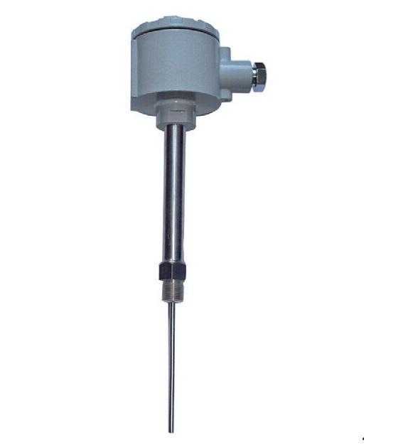
Explosion-proof Thermocouple ( Thermal Resistance) with Temperature Transmitter
Application
It is usually connected with display meter, recording meter, computer, etc. to directly measure temperature of liquid, vapor, gas and solid surface ranging from -200℃ to 1300℃ with explosives such as hydrocarbon on production spot, with output of 4~20mA.
Features
1.Double wire system output of 4~20mA,good anti-interference performance
2.Spare cost on compensational wire and temperature transmitter installation
3.Wide measuring range
4.Automatic compensation at cold end, non-linear rectifying circuit
Operation Theory
Pyroelectric potential change tested with the thermocouple (thermal resistance)results in imbalance signal through electrical bridge of temperature transmitter. The signal transforms into D.C. 4~20mA signal after being amplified and is transmitted to working meter, then working meter shows relevant temperature value.
Main Technical Parameters
Executive Standard
IEC584
IEC751
JB/T7391-1994
Measuring Range & Tolerance
Thermal Resistance
| Type | Graduation | Measuring Range ℃ | Accuracy | Tolerance | |
| WZPB | Pt100 | -200~+500 |
A級(jí) B級(jí) |
±(0.15+0.002) ltl ±(0.30+0.005) ltl |
|
| WZCB |
Cu50 Cu100 |
-50~+100 | |||
| --- | ±(0.30+0.006) ltl |
Thermocouple
| Type | Graduation | Tolerance Class | |||
| I | II | ||||
| Tolerance Value | Measuring Range °C | Tolerance Value | Measuring Range °C | ||
| WRNB | K | ±1.5°C | -40~+375 | ±2.5 °C | -40~+333 |
| ±0.004ltl | 375~1000 | ±0.0075 ltl | 333~1200 | ||
| WRMB | N | ±1.5°C | -40~+375 | ±2.5°C | -40~+333 |
| ±0.004 ltl | 375~1000 | ±0.0075 ltl | 333~1200 | ||
| WREB | E | ±1.5°C | -40~+375 | ±1.5°C | -40~+333 |
| ±0.004 ltl | 375~800 | ±0.004 ltl | 333~900 | ||
| WRFB | J | ±1.5°C | -40~+375 | ±1.5°C | -40~+333 |
| ±0.004 ltl | 375~750 | ±0.004 ltl | 333~750 | ||
| WRCB | T | ±1.5°C | -40~+125 | ±1°C | -40~+133 |
| ±0.004 ltl | 125~350 | ±0.0075 ltl | 133~350 | ||
4~20mA Loading Resistance :250 1/2
Transmission Conductor Resistance: 100 1/2
Output Way:
Double Wire System
Tolerance Class:
0.1;0.2;0.5
Power Supply:
24V D. C. ±10%
Protection Class:
IP65
Insulation Resistance:
Insulation resistance between wiring terminal and outer shell shall be to less than 50 1/2.
Thermal Response Time:
We use t 0.5 to represent the time needed for current output signal of instrument to change to 50% of step change of temperature.
When step response time of temperature transmitter is no more than 1/5 of thermal response time t 0.5 of thermocouple (thermal resistance), thermal response time of thermocouple (thermal resistance )is considered as that of the instrument.
When step response time of temperature transmitter is no more than 1/2 of thermal response time t 0.5 0f thermocouple (thermal resistance), thermal response time of temperature transmitter is considered as that of the instrument.
Basic Error:
The basic error shall be no more than total error of thermocouple and temperature transmitter.
Operation Environment
| Environment Grade | Temperature ℃ | Ralative Humidity % | Air Pressure kPa |
| Cx1 | -25~+55 | 5~95 | 86~106 |
| Cx2 | -25~+70 | ||
| Cx3 | -40~+80 |
Operation temperature of temperature transmitter is the sum of shell temperature rise caused by support tube and ambient temperature, PLS see the following figure for shell temperature rise caused by support tube:
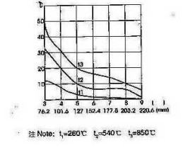 Note: t1=260℃ t2=540℃ t3=850℃
Wiring Method
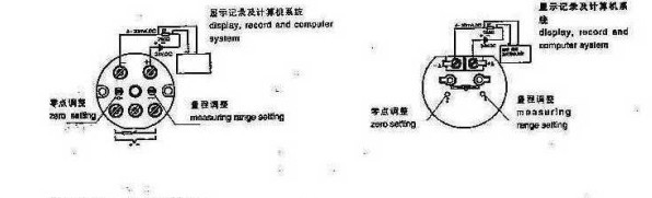
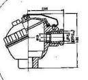
Junction Box
Type Naming Method
| W | Temperature Instrument | |||||||
| R |
Category R Thermocouple |
|||||||
| Z | Z Thermal Resistance | |||||||
| Thermal Element Material | ||||||||
| M | M NiCrSi-NiSi | |||||||
| N | N NiCr-NiSi | |||||||
| E | E NiCr-CuNi | |||||||
| F | F Fe- CuNi | |||||||
| C | C Cu- CuNi | |||||||
| P | P Pt | |||||||
| C | C Cu | |||||||
|
|
B Temperature Transmitter | |||||||
|
|
Mounting &fixing | |||||||
| 1 Without fixing device | ||||||||
| 2 Threaded connector | ||||||||
| 3 Movable Flange | ||||||||
| 4 Fixed flange | ||||||||
| 5 Elbow tube connector | ||||||||
| 6 Fixed threaded Cone connector | ||||||||
| 7 Straight tube connector | ||||||||
| 8 Fixed threaded tube connector | ||||||||
| 9 Movable threaded tube connector | ||||||||
| Junction box | ||||||||
| Anti-spray Type | ||||||||
|
|
Protection Tube Diameter | |||||||
| 0Φ16 | ||||||||
| 1Φ20 | ||||||||
| 2Φ16 High Al Content Tube | ||||||||
| 3Φ20 High Al Content Tube | ||||||||
|
Measuring End G Variable cross section |
||||||||
| W | R | N | B | 2 | 2 | 0 | G | Model example |
Last:Without the Next:with straight tube connector